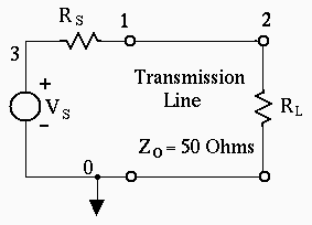
Figure 1 Transmission Line Circuit

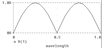
Figure 2 Standing wave with a shorted load. The input voltage is plotted as a function of the length of the line in wavelengths.

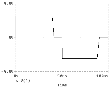
Figure 3 Transmission line pulse response is shown.
Lab 2 Transmission Line Simulation
 Figure 1 Transmission Line Circuit
|
Standing wave simulation
The standing wave simulation shown in Figure 2 was achieved using the following input file describing the circuit in Figure 1.
        Transmission Line Simulation
*
.PARAM wavelength= .75
Vs  3 0 AC 1
Rs  3 1 50
Rl  2 0 1e-3
T1  1 0 2 0 Zo=50 F=1MHz NL={wavelength}
.STEP PARAM wavelength  0  1 .05
.AC LIN 1 1MHz 2MHz
.probe
.end
The transmission line described by T1 is a bidirectional delay line,
with two ports. One at nodes 1 and 0 and a second at nodes 2 and 0.
The characteristic impedance is 50 ohms. The length of
the line is given in wavelengths, NL. Here NL is parameterized so the
length of the line can be stepped from 0 to 1 wavelengths. The STEP command
causes 21 transmission lines with lengths from 0 to 1 wavelength to
be simulated. Each simulation is done at only one frequency, 1MHz.
Pulse Response
The following input file resulted in the transmission line pulse response shown in Figure 3.
        Transmission Line Simulation
*
Vs  3  0  PULSE(0 5 0 0 0 50n 100n)
*Pulse train period=100ns, pulse width =50nS
Rs  3  1  50
Rl  2  0  1e-3
T1  1  0  2  0  Zo=50  TD= 20ns
.TRAN  0.1n  100n
.probe
.end
The transmission line is driven by a 5 Volt pulse 50 nanosec wide that repeats
every 100 nanosec. The length of the line is described by the oneway transit
time, TD=20ns.
Initially the 5 V pulse divides between RS and the input impedance to the line without reflections, Zo=50 Ohms. This results in an initial input voltage of 2.5V. The pulse travels down the line. A reversed polarity pulse is reflected from the short circuit at the load. After 40 nS this reflected pulse returns to the input where it subtracts from the input voltage. The input pulse is still present. The input voltage is the sum of the input and reflected pulses. This is zero volts. It lasts from 40 nS to 50 nS. At 50 nS the input pulse goes to zero, leaving only the reflected negative 2.5 V pulse. This continues for another 40 ns (90 ns) until the reflection goes to zero.
Exercises
If signals travel at the velocity of light, what is the length of the line?